


Design and Supply of Technology Equipment for Vacuum Sewerage System
Our services include: Design, concept development, budget estimation, pump station and network design, master planning, auditing systems, project management, system maintenance, asset management support, and training.
The vacuum sewerage system utilizes the differential air pressure and gravity forces to quickly transport wastewater in the network from collection pits/holding tanks to the central collection tank, and then to the discharge point. Each batch of wastewater enters the vacuum system when the valve is open in the collection pit, and the wastewater is suctioned into the vacuum pipe. The valve remains open for a short time after all wastewater is sucked from the collection pit, allowing air to enter the suction pipe and push the wastewater towards the vacuum pumping station.
A vacuum control valve of 90mm (3 inches) is installed in the collection pit, which collects and stores the wastewater.
When approximately 40 liters of wastewater from over four households flow into the holding tank, a sensor tube in the wastewater tank is activated to open the valves, allowing both wastewater and air to enter the vacuum pipe at a speed of 4-6 meters per second. This suction tube also ensures that no odor remains in the collection pit, preventing gas explosions.
At this stage, no power source is required, as all operations are performed using compressed air.

PE Collection Pits are commonly used because they provide a separation between the wastewater collection pit and the valve, ensuring that workers do not come into direct contact with wastewater. The position of the valve is always within reach to facilitate easy operation for workers without issues regarding limited space.
The valve is primarily made from polypropylene material mixed with fiberglass and has an internal diameter of 78mm (3.07″). It is designed with a lifespan of 50 years, requiring only minor part replacements every 10 years.
The valve and controller are designed to be transparent, ensuring simplicity and convenience for operators, allowing easy removal of parts from the valve body with a simple sliding lock. The top of the valve body can be easily loosened for cleaning in case of any unusual blockages.
The valve is also designed with monitoring capabilities, allowing comprehensive tracking and evaluation. This enables operators to remotely check for any errors, parts corrosion, or leakage issues.
The vacuum pipe connecting the collection pit to the vacuum pumping station transports wastewater and air.

The Vacuum Pipeline can be made of PE pipes or PVC pressure pipes, which are buried shallowly underground with a slope of 1/500. Contractors typically install vacuum wastewater pipelines in a sawtooth pattern to transport wastewater in steps or uphill, preventing the pipes from being laid too deep. However, the more steps there are, the greater the hydraulic loss, which limits the overall pipeline length.
A well-designed system can extend up to 5 km from the vacuum pumping station in different directions. It is crucial to have collection pits evenly distributed across the entire drainage area and along the vacuum pipelines to ensure sufficient air intake, which serves as the system’s energy source.
Most systems are designed with 3-5 pipelines to evenly distribute flow and ensure efficient operation.
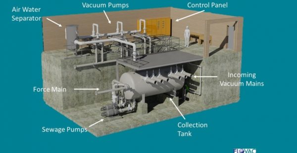
The vacuum pumping station consists of:
- A wastewater collection tank
- Pumps to transport wastewater to the treatment plant
- A control system for automating the pumping station
- Vacuum pumps to maintain negative pressure within the vacuum pipelines.

The vacuum pressure typically ranges between 0.5 to 0.7 bar.
On average, only one vacuum pumping station is required per drainage basin.
A vacuum pumping station can transport wastewater up to 10 miles or even further to the treatment plant if necessary. The key factor is selecting the correct pump size and pipeline diameter to meet the system’s requirements.

